Dimensional criteria for the design of enclosures - Part two
For panel boards addressed to Hazardous Areas In this second part, we intend to describe the criteria for the mechanical dimensioning of...
In this second part, we intend to describe the criteria for the mechanical dimensioning of enclosures addressed to potentially explosive atmospheres.First of all, it’s important to have the sizing parameters that must be provided by customer at the time of size request which are the basis for continuing the technical analysis. These parameters can be summarized as follows:
- Method of protection:
- Ex d IIB, with direct entry of cables;
- Ex d IIB+H2, with direct entry of cables (presence of hydrogen);
- Ex d IIC, with direct entry of cables;
- Ex d IIB, with indirect entry of cables;
- Ex d IIB+H2, with indirect entry of cables (presence of hydrogen);
- Ex d IIC, with indirect entry of cables.
- Temperature Class T1, T2, T3, T4, T5, T6, in accordance with IEC 60079-1 or EN 60079-1 or CEI EN 60079-1 Standards and according to the place of installation (this parameter will be discussed in a following article relevant to the electrical dimensioning).
- Ambient temperature ((this parameter will be discussed in a following article relevant to the electrical dimensioning).
- Description of the composition of the Panel Board and the electrical characteristics.
- Dimensioning of pre heater of the enclosure (this parameter will be discussed in a following article relevant to the electrical dimensioning).
In consequence of the above parameters, we can proceed to the mechanical sizing of the enclosure, analyzing the following four aspects.
According to the certification parameters, the designer analyzes the possibility to stay the entries (for size and quantity) required by the client.For this test, two fundamental parameters must be taken into account:
- the maximum drilling surface of the wall;
- the minimum distance for the positioning of the entries, both towards the border of the maximum drilling and towards the adjacent entry/entries.
The maximum drilling surface of the wall is a parameter attributable to the specific size of the enclosure and, then, consequential to the quantity of components to be placed inside the enclosure. Therefore, one of the two parameters must be evaluated along with the “Verification of the equipment positioning inside the enclosure”.
The minimum distance of entries positioning is another parameter that should be carefully analyzed. Indeed, this minimum distance, defined by certificate parameters, in addition to ensuring the mechanical strength of the perforated wall, allows the installer to proceed with the proper tightening of the components into such entries (e.g., cable glands, plugs, reducers and/or adapters). Furthermore, the minimum distance to the boundaries of the maximum drilling is important to ensure non-interference with the thickness of the adjacent wall.
Have a look at the criteria which is usually adopted for such sizing.
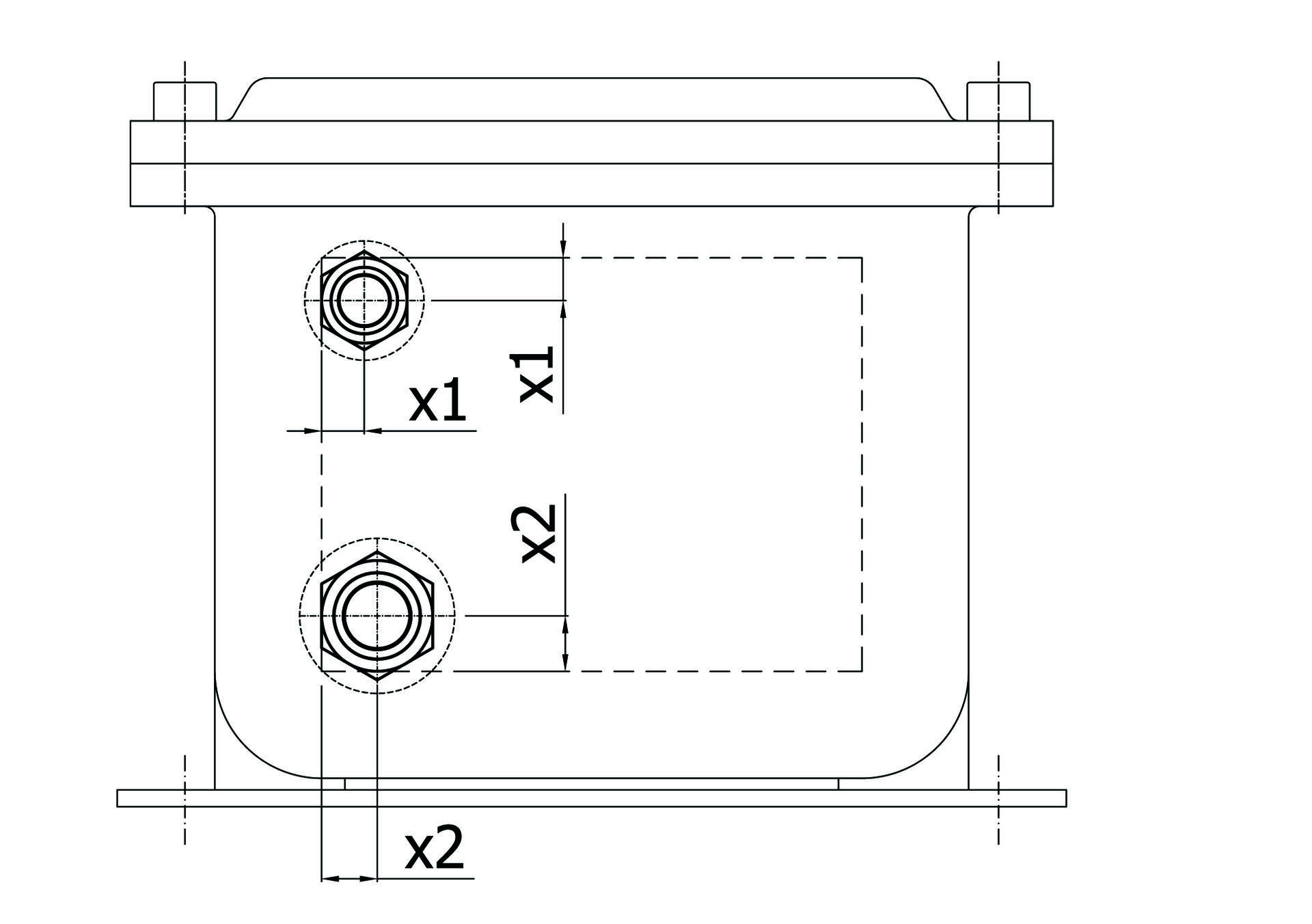
The minimum positioning distance towards the borders of the maximum drilling can be better understood from the following illustration:

Stated as certain the dimensions "a" and "b", which are specific for each size of enclosure, the dimensions "x" will be determined according to the size of the component that you plan to place. As you can see from the drawing, it’s not necessary to comply with the dimensions marked by the hatching but it will be sufficient that the relative size of the outer diameter of the mechanical IP gasket (this only for the Metric threads which need gaskets) does not exceed (total support on the flat surface of the wall) over the drilling limit. On the other hand, for the conical threads, as it’s not necessary to lean on the surface of the wall, you can align the diameter of the hole to the edge of the drilling surface (x = ½ minimum thread).
Obviously, you have to consider the largest dimension "x ..", if the entries are of different sizes.
We assume that a customer made the following request. A lighting panel board, consisting of:
- n° 1 main incoming line 400Vac, 3Ph+N+Pe suitable for 20 kW nominal power and 10 kA breaking capacity;
- n° 10 output light branches, 230Vac, 2 Poles 2kW and related ELCB (earth leakage circuit breaker) 30mA;
- n° 1 XLPE/SWA/PVC of 4G 25sqmm feed armored cable, with outer armor diameter ø 27,6mm and inner armor diameter ø 20,8mm;
- n° 10 XLPE/SWA/PVC of 3G 6sqmm, outgoing feed armored cables for lighting circuits, with outer diameter ø 16,9mm and inner diameter ø 12mm.
- Environmental conditions: ambient temperature 45°C, height above sea level 30m.
- Temperature Class: T6.
- Method of protection: Ex d IIB.
- Incoming and outgoing cables: on the short lower side.
- Entries Threads: Metric ISO 965-1 / 965-3, in accordance with IEC 60079-1 standard.
- Degree of mechanical protection: IP 65.
The first dimensional analysis is related to the sizes of the cable glands, depending on the diameters of the cables required.
- For the incoming feed cable, it’s necessary a double seals cable gland, type REVD3, size M32, with outer armor sealing ring range of 24 ÷ 31mm and inner armor sealing ring range of 18 ÷ 24mm.
- For the outgoing feed cables it’s necessary a double seals cable glands, type REVD2, size M25, with outer armor sealing ring range of 16÷24mm and inner armor sealing ring range of 12÷18mm.
The second dimensional analysis is the dimensioning of the circuit breakers, as the customer's request is in value of power (kW).
- For main circuit breaker, you will have a rated current of 40A (I) at an operating voltage of 400VAC three-phase plus neutral (I = P/(V x 1,73 x µ x cosφ)).
- For outgoing lighting circuit breakers, you will have a rated current of 10A (I) at a operating voltage of 230VAC one phase plus neutral (I = P/V).

As you can see, whether adopting the "linear" or "triangle" criterion, there is the same type of capacity on the lower short side, with the possibility of a greater spacing than the minimum distance of coupling with the "triangle" disposal.For sizing purposes, as shown in the drawing, is considered a distance that is not the maximum size of a single cable gland, but rather the minimum distance, as provided in the certificate, suitable for clamping with standards tool as a wrench.
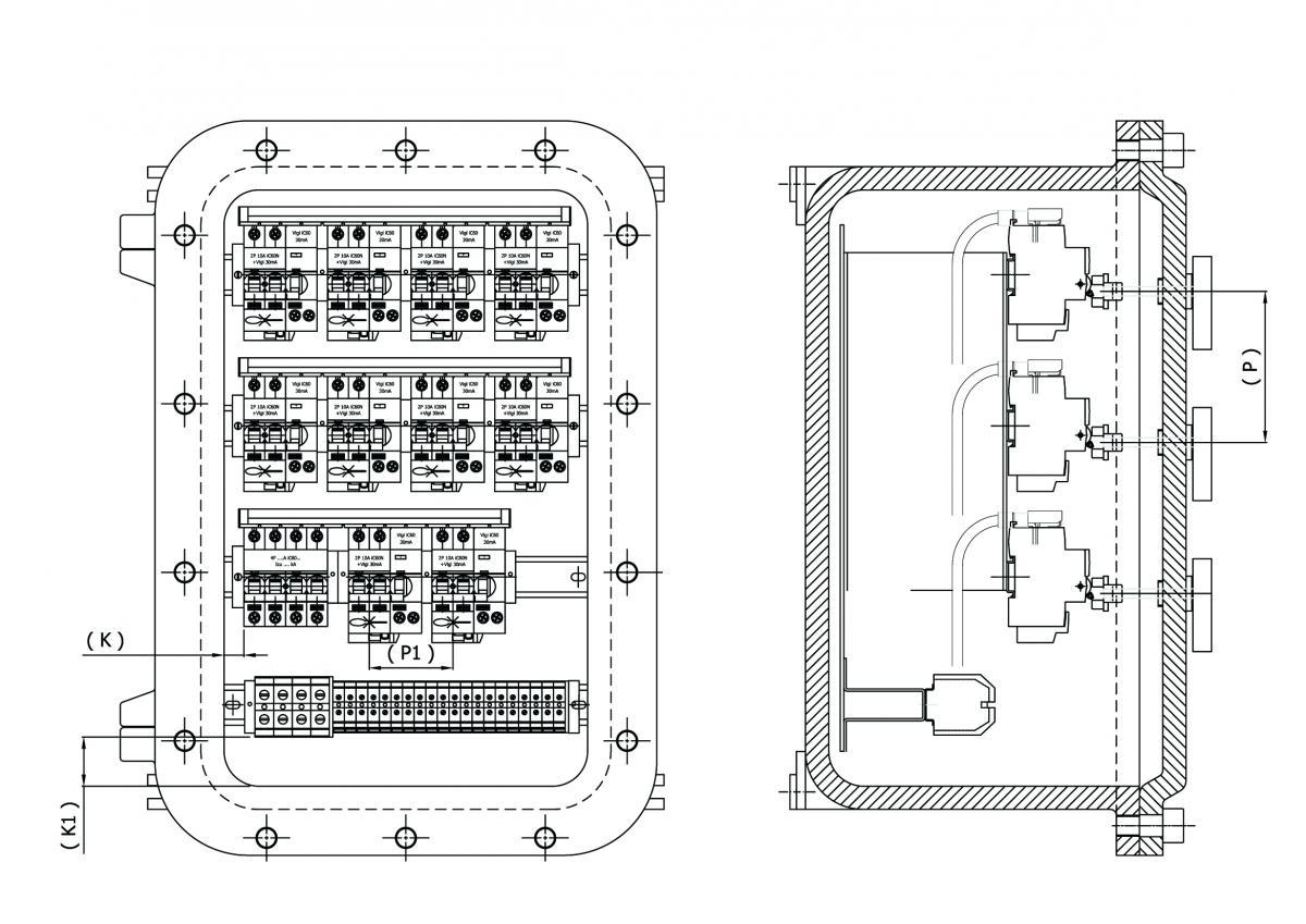
The number of control devices that can be placed on the lid of the enclosure is a test that involves multiple issues, both mechanical and electrical. These are problems which require a correct approach in order to check that there is no interference with what will be housed inside the enclosure.
For illustrative and non-limiting purposes, we give below a short list of variables that are involved in this type of sizing:
- minimum distance (P) applicable to operators on the cover, distance defined in the documentation of the certificate;
- minimum distance (P1) applicable to the single component to be housed within the enclosure;
- minimum distance (K) to be respected from the component to the inner wall of the enclosure;
- minimum distance (K1) to keep from the terminal block to the wall of the input/output cables.
As you can well understand, consider only the minimum distance between the holes on the lid is sometimes not enough. In fact, if we consider the use of the enclosure as a signal and control panel, so without equipment to be placed inside the enclosure unless the terminal strips for input/ output cables, should be sufficient to check the minimum distance between the operators and their depth, in order to not interfere with the dimensions of the terminal strip.
The maximum allowable dissipation is a parameter intrinsic to the size of the enclosure which varies according to the ambient temperature and the class temperature (ambient temperature and class temperature values that must be provided by the customer at the time of the size request).
Considering the quantity of equipment required and the coefficient of contemporaneity of the same in continuous operation, you can then proceed to the check, noting the dissipation of such equipment and terminal blocks. These values can be detectable in the technical documentation of the manufacturers of such equipment (values as dissipated power at a specific temperature, directly expressed in Watts, or as resistance value, expressed in Ohm).
If these values are expressed in Watts, it’s enough to make the sum of these values, only for equipment working in parallel and simultaneously.
If these values are expressed in Ohms, it’s necessary to convert the resistance value in power value in Watts, with a simple formula: P (W) = r x I2, in which "r" is the resistance value declared by the manufacturer "I" is the nominal working current under operating conditions.
The sum of P1 + P... n will provide the total value of the dissipated power (Pt) of the units operating in parallel and contemporary.
This value is then compared with the value of maximum dissipation provided in the certificate, at specific ambient and class temperatures.
If the "Pt" value will be less than the expected certification value, the sizing will be correct and suitable for the customer's request. On the other hand, if the "Pt" value will be higher, we should proceed to a dimensional review with the use of an enclosure that meets the dimensional proportion.
We conclude this second part saying that all activities of electro-mechanical sizing are the prerogative of the manufacturer of the Panel Boards in explosion-proof execution: analysis, calculations and the resulting executive project are of its responsibility, putting the plate certifying the compliance with the relevant Standards.In the newsletter of the next month, we’ll analyze how important is the sizing of the electrical conductors to be used as "wiring" inside the distribution panels and starters, which will then be installed in explosion proof areas.