Dimensional criteria for the design of enclosures - Part one
For panel boards addressed to Hazardous Areas, ‘Ex d’ and ‘Ex e’ executions Many customers advise us the need to have a dimensional...
Many customers advise us the need to have a dimensional criteria for enclosures used as distribution panels, motor starters, control, signaling and marshalling boxes.
Since this is a topic that covers many different aspects of dimensional character/construction, with this first part of the topic we intend to highlight the variables inherent to the proper sizing of enclosures suitable for installation in hazardous areas, from the mechanical and electrical point of view.
In order to make a correct sizing of enclosures for the uses described above, it is essential that all the parameters are systematically taken into account and used as a method of calculation for determining the size of such enclosures.
Considering that these enclosures must be suitable for installation in hazardous areas (‘Ex d’, ‘Ex de’) and they are, therefore subject to certification by qualified entities recognized at international level, is of utmost importance that these sizing meet all the parameters set by the reference Standards, such as:
- IEC 60079-0 / EN 60079-0 / CEI EN 60079-0: Explosive atmospheres – Part 0: Equipment – General requirements;
- IEC 60079-1 / EN 60079-1 / CEI EN 60079-1: Explosive atmospheres – Part 1: Equipment protection by flameproof enclosure “d”;
- IEC 60079-7 / EN 60079-7 / CEI EN 60079-7: Explosive atmospheres – Part 7: Equipment protection by increased safety “e”;
- IEC 60079-14 / EN 60079-14 / CEI EN 60079-14: Explosive atmospheres – Part 17: Electrical installations design, selection and erection.
This task belongs mainly to the manufacturer of such equipment, as prescribed by the regulations listed above; however, we intend to provide our customers a wide description of the criteria that we usually take to realize the sizing.
These types of enclosures, in succession called "Panel Board", which must be suitable for installation in explosion-proof areas, industrial plant, on drilling/production plant (Off-Shore), on flotation devices used in the drilling and/or production (FPSO), are divided mainly into the following types:
- Power distribution Panel Board
- Lighting distribution Panel Board
- Motor operated valve (MOV) Panel Board
- Motor starting Panel Board
- Local control Panel Board
- Marshalling Panel Board
- Feeder electrical tracing Panel Board.
The types of construction for these Panel Boards consist essentially of:
- “Directly” cable entry, type (‘Ex d’ execution)
- "Indirect" cable entry, type (‘Ex de’ execution).
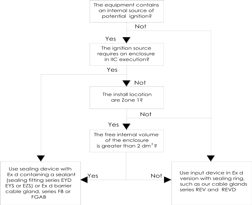
The "directly" execution provides for the entry of cables directly to the Panel Board in ‘Ex d’ execution, with the use of sealed cable glands that does not allow for a possible explosion within the Panel Board to spread outside of it. In this case, the choice of the cable or sealing fitting shall meet the requirements of the Standard, as in Figure 1.
Typical of “directly” entry in ‘Ex d’ execution.
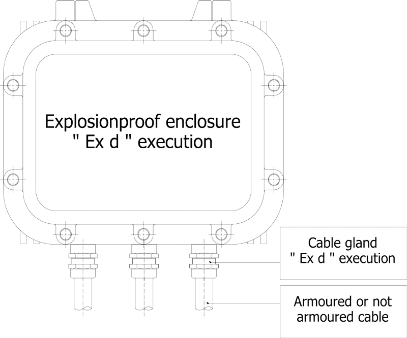
Figure 1
The "indirect" execution involves the use of an increased safety "Ex e" junction box for input/output cables, within which are housed the increased safety terminal blocks. From this enclosure are derived all the links from and to the explosion-proof enclosure in "Ex d" execution. The passage between the two enclosures will be through sealed locking devices and/or sealed bushings, always in ‘Ex d’ execution. In this case, the choice of the sealing fittings and/or the sealed bushings has to comply with the requirements of standard, such as from the above Figure 1.
Typical of “indirectly” entry in ‘Ex de’ execution.

One of the primary problems for the mechanical dimensioning is to verify that the quantities of the entries of the in/out cables from the panel are correctly dimensioned and arranged, according to the parameters of the certificate. This problem is attributable to the maximum possible drilling of each wall and/or of the cover that are a focal point for this dimensioning.
Since many types of enclosures require the verification of the maximum allowable quantity of entrances, please refer to the manuals for installation, use and maintenance of our enclosures series EJB..., EJB .. A..., EJBX ..., GUB ..., EJBE ..., EJBXE ...,... GUBE..., GUBE.. H..., CCA..C... and CCAI... leaving the specific description of this sizing to a following dissertation.
Another problem is to check the quantity of devices installed inside of these enclosures and the minimum respect distances, always in accordance with the parameters of the certificate and, not least, to the specifications required by customers. Also for this test, refer to the manuals for installation, use and maintenance mentioned above and a following dissertation.
- "Minimum respect distance" means the minimum distance of the component and/or equipment to be inserted into the enclosure, towards the wall of the housing itself and/or to the component to which it has to be joined, in order to allow the component and/or equipment a proper heat dissipation and, consequently, its proper functioning in accordance with the dimensional parameters of the constructor.
- "Inter distance between the various internal components" means the physical distance that must be left between a component and the adjacent one, in order to allow for a proper thermal dissipation and to not reduce the power current due to the extreme proximity to another component. This distance can be checked in the manufacturer's technical documentation.
- "Least inter distance of entries on the walls of passage" means the minimum distance provided in the technical documentation and certificate, in respect of the maximum drilling surface in accordance with the technical documentation.
The problems related to a proper electric dimensioning are numerous and can be summarized as follows:
- dimensioning according to the rated operational current (Ie) of the equipment and/or terminal strips;
- dimensioning according to the breaking capacity (Icn) in kA and time of intervention (s);
- choice of the tripping curves of thermal-magnetic or magnetic only circuit-breakers;
- dimensioning as a function of temperature, according to temperature class, according to the subdivision as per IEC 60079-0 or EN 60079-0;
- dimensioning as function of electric coordination/filiation/selectivity;
- dimensioning according to the maximum allowable power dissipation (W);
- dimensioning as function of specific let-through energy on the electrical conductors;
- dimensioning as function of the coefficient of contemporaneity;
- dimensioning of the auxiliary transformer necessary for secondary circuits;
- the nominal voltage (Ue);
- the insulation voltage (Ui);
- the nominal frequency (Hz);
- the electromagnetic compatibility of components and/or electrical equipment.
Let's look for each issues which actions must be developed.
The rated operating current (Ie) is the value of current (in amps) that the components absorb in operation, continuous operation 24 hours and it is the value that will be considered for a correct dimensioning of the electrical conductors inside of the enclosure. It should be considered that this value must be communicated by client at the time of dimensioning request and, depending on the temperature and the temperature class in which the Panel Board will operate, the designer will have to properly size the conductors and components based on these data.
- "Thermal rated current (Ith)"means the rated current that the component is able to withstand during a continuous service and to a reference temperature. These data can be found in the technical documentation of the manufacturer of such components.
- "Rated current (Ie)" means the rated current that the project has provided to operate to the component (current that normally differ much from the thermal nominal current). This nominal current (Ie) must obviously be compared to the temperature in which the component will operate (this temperature is NOT the temperature but is the temperature of the project but derated for use in confined space and with little or no ventilation).
The breaking capacity (Icn) in kA and time of intervention (s) are basic values for the correct sizing and must be communicated by client at the time of dimensioning request.Such values determine all the electrical dimensioning and, therefore, are considered fundamental for the analysis of calculation.
- "Breaking capacity (Icn)" means the rated short-circuit capacity of the component, in accordance with CEI EN 60947-2 standard (value expressed in kA) and the response time in seconds.
The choice of trip curves of thermo-magnetic or magnetic circuit-breakers is also an important part in the sizing and it’s a parameter, such as the breaking capacity (Icn), which must be communicated by client at the time of dimensioning request.
- "Tripping curve breakers" means the characteristic curve for type of use as following:
- Curve B: When there’s a generator able to provide only a low short-circuit current.
- Curve C: Standard loads.
- Curve D: When the starting current is of high intensity (5 to 7 times the rated current).
- Curve K: Protection of users with high inrush currents (motors, transformers).
- Curve Z: Protection of electronic circuits.
- Curve MA: Motor protections (circuit breakers with magnetic function only).
The sizing depending on the environment temperature, according to temperature class and as per the subdivision of IEC 60079-0 or EN 60079-0 standards, is a further important parameter for a correct analysis. In fact, the current capacity of the devices is strongly influenced by the variation of temperature, which in turn undergoes a reduction in function of the temperature class, class of temperature that must be communicated by client at the time of dimensioning request.
- “Temperature” is intended the project value that must be communicated by clientat the time of dimensioning request.
- “Temperature class” means the value, expressed in °C, to which refer for the control of the maximum surface temperature that the outer surface of the housing can reach for its correct operation in an environment, classified as:
- T1 = 450°C
- T2 = 300°C
- T3 = 200°C
- T4 = 135°C
- T5 = 100°C
- T6 = 85°C
- T1 = 450°C
- T2 = 300°C
- T3 = 200°C
- T4 = 135°C
- T5 = 100°C
- T6 = 85°C
temperatures which must not be exceeded due to overheating of internal components.
The coordination of electrical/filiation and selectivity is another of the dimensional variables that must be considered for the calculation. In fact, if you opt for sizing all Thermal-magnetic circuit breakers according to the breaking capacity required, provided that it would be technically correct, you would have a overheating of components and electrical conductors, according to this value. However, the construction technologies have made that, with a proper coordination of the circuit breakers, you can get, downstream of the main circuit breaker, a lower short circuit current and, consequently, adopt downstream circuit breaker suitable for the underlying value. This, in addition to allowing a suitable dimensioning, leads to a not negligible economic saving.
The sizing according to the maximum allowable power dissipation (W) is essential for a proper sizing because it affects the electric parameters of the certificate. In fact, in order to get the certificate, a series of tests have been performed in order to verify the maximum allowable thermal dissipation in the enclosures, as a function of both the temperature class and the ambient temperature. For this test, therefore, have to be taken into account the equipment individual dissipation that will be installed inside the enclosures and their sum, which mustn’t, in any case, exceed the expected value of the certificate. Obviously these values, detectable from the technical documentation of each manufacturer, will have to be remeasured as a function of the temperature and the downgrading for installation under a prevented ventilation.
- "Maximum power dissipation of the component and/or equipment, at the temperature of the project (W)" means the value of thermal dissipation of that object. This value may be found in the manufacturer's technical documentation and downgraded or outclassed in terms of its value, to a specific temperature to bring back to the temperature value of the project. You should observe a greatest attention to this sizing, whereas normally the components and/or equipment have a value of thermal dissipation for an installation in free air at a temperature of 20°C or other temperature stated by the manufacturer.
The verification of the energy which pass through the electrical conductors (I2t = K2S2) is of great importance for the purposes of a correct dimensioning because all the currents caused by a short circuit that is present in any point of the circuit, must be interrupted in a time not greater than that which brings the wires to the allowable temperature limit. Therefore, it will be necessary to test the conductors based on that value. Such value of I2t must be specified by the manufacturer of the protective device.
- "Through energy of electrical conductors" means that the electrical conductors must be properly sized to prevent that, overheating generated during the working or during the event of over current due to a malfunction (short circuit), may be the cause of the enclosure surface temperature increase and, consequently, source of ignition the outer atmosphere. This sizing must be depending on the energy I2t which pass through each wire in extreme short-circuit. This value can be found in the manufacturer's technical documentation but it needs a specific next calculation, depending on the temperature class and on the temperature of the project.
The coefficient of contemporaneity is another of the parameters necessary for the correct electrical sizing. This coefficient must be communicated by the clientat the time of dimensioning request. It determines, in function of the simultaneous operation of the equipment, the value of the current that must be considered for sizing the electrical conductors. For contemporary, we mean the ability to be operative in continuous parallel service.
The dimensioning of the auxiliary transformer for secondary circuits, where necessary and in the presence of auxiliary circuits generated within the Panel Board, is another of the analysis parameters. This calculation is performed by summing the loads and the contemporaneity factor that they can have, considering also the peak of maximum absorption of the biggest start-up device in addition to the sum of the total loads.
The nominal voltage (Ue) is the value of the operating voltage that defines the characteristics of the use of a specific circuit. All electrical equipment that are going to be used, shall be constructed in order to be capable of operating at this voltage value, with the tolerances set by the reference standard which in principle correspond to ± 10%, unless otherwise specified in the customer request.
The insulation voltage (Ui) is the efficient value of the insulation test voltage assigned by the manufacturer of the component and/or equipment, which determines the resilience of its isolation and surface distances (the shortest distance measured along the surface of an insulator interposed between two conductive parts).
The nominal frequency (Hz) is the frequency value at which report the operating conditions of the system. All electrical equipment that are going to be used, shall be constructed in order to be capable of operating at this frequency, with the tolerances set by the reference standard which in principle correspond to ± 5%, unless otherwise specified in the customer request.
The electromagnetic compatibility of the components and/or electrical equipment is one of the requirements in the use of electrical equipment which must be taken into consideration.
- "Electromagnetic compatibility of components and/or electrical equipment" means that, in addition to the various requirements of the ATEX and IECEx Directives, all components and/or electrical equipment must also meet: the machinery Directive 2006/95/EC, the Directive on electromagnetic compatibility (EMC) (2004/108/EC), the local electrical reference such as EN 61547 or IEC 61547 (intrinsic immunity) and the protection from over-voltage transients networks, according to the values specified in the EN 61547 or IEC 61547 Standards (immunity).
We conclude this first part saying that all activities of electro-mechanical sizing are the prerogative of the manufacturer of the Panel Boards in explosion-proof execution: analysis, calculations and the resulting executive project are of its responsibility, putting the plate certifying the compliance with the relevant standards.