The 'Ex d' type of protection: explosion-proof joints
Explosion-proof joints are one of the basic aspects of the protection offered by an equipment or an explosion-proof enclosure. For this reason, understanding their function is a prerequisite for the correct use and the proper maintenance of all electrical devices that adopt this type of protection.
by Andrea Battauz, R&D Project Engineer of Cortem Group

Introduction
A typical feature of equipment with 'Ex d' type of protection is the presence of explosion-proof joints. The explosion-proof enclosures need to be opened, initially for the installation of the components inside and periodically for ordinary or extraordinary maintenance. They are therefore equipped with lids or doors. In other situations, there are moving parts that intersect the explosion-proof enclosure. We think of a shaft of an electric motor or of the levers/buttons that activate the opening and closing of the switches inside the panels. In both situations, the explosion-proof enclosure is made up of several components which, assembled, must guarantee the maintenance of the 'Ex d' type of protection.
The surfaces along which these components are in contact have a guaranteed and specific play. Through these interstices, in fact, it must be ensured that any explosion inside the explosion-proof enclosure is not able to ignite the external atmosphere.
Therefore, the corresponding contact surfaces of two parts of an enclosure are defined as an explosion-proof joint, through the interstices of which the propagation of an explosion inside the enclosure to the surrounding explosive atmosphere stops.
In the Figure 1 here above an example of flue gas output from a flanged joint (EJB-3).

Most common types of explosion-proof joints and connection with the gas group of the equipment
The most popular explosion proof joints are cylindrical, threaded or flanged [1]. They are placed in the contact planes between bodies and lids, in the threads of threaded lids, in the cylindrical surfaces of the cylindrical joints. The flanged joints and the cylindrical ones are provided with fixing screws, while the threaded joints are fixed with the same thread that constitutes the joint. In the latter case there is a fixing dowel with an anti-loosening function.
As can be seen from figure 2 here above, there is a link between the type of explosion-proof joint and the gas group of the appliance. The flanged joints, in fact, are put in crisis when they must hold back the passage of flame of gases such as hydrogen and, above all, acetylene. For this reason, a site with gases classified as IIC has always required equipment with threaded or cylindrical explosion-proof joints and, consequently, equipment contained in round or square enclosures. Only recently new types of joints obtained with special mechanical processing have allowed the creation of rectangular enclosures suitable for the gas group IIC [2].
Figure 2 also shows how the enclosures with flanged flat joint can be certified for group IIB + H2. In this case, their use is extended to environments with the presence of hydrogen, a situation of no secondary importance if we consider that hydrogen is produced, for example, in the charging points of forklift batteries.

Figure 3: section of a housing with lid equipped with a cylindrical joint and the path followed by the flue gases in red
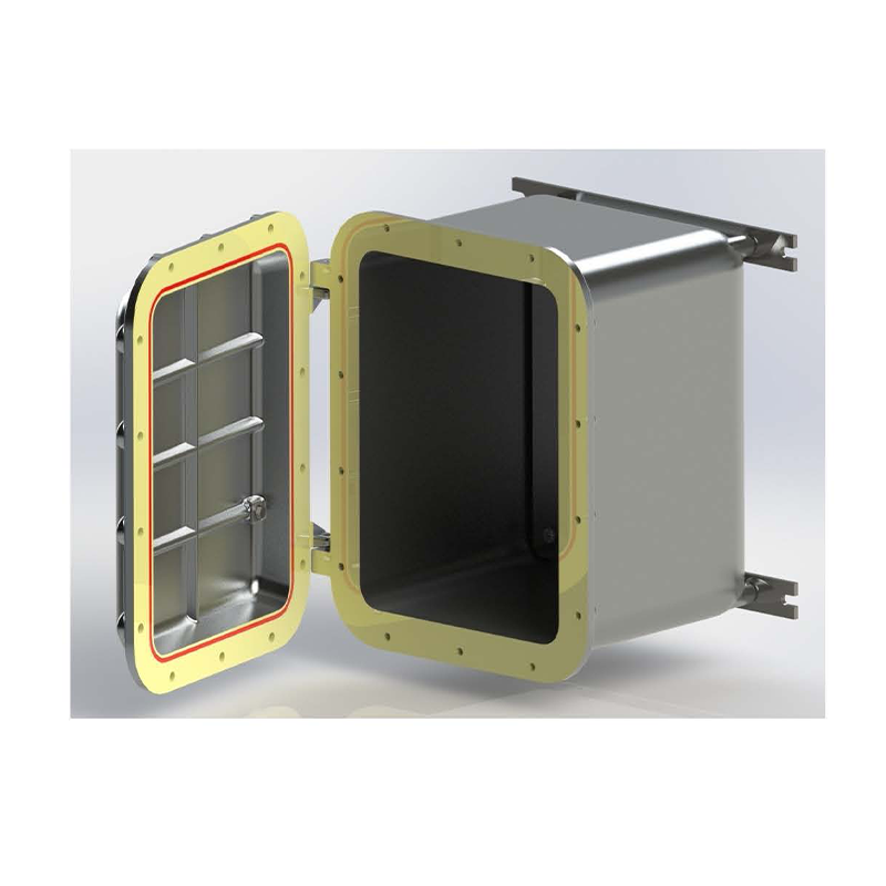
Figure 4: Flanged explosion-proof coupling of an Cortem EJB-3 in yellow
Principle of operation
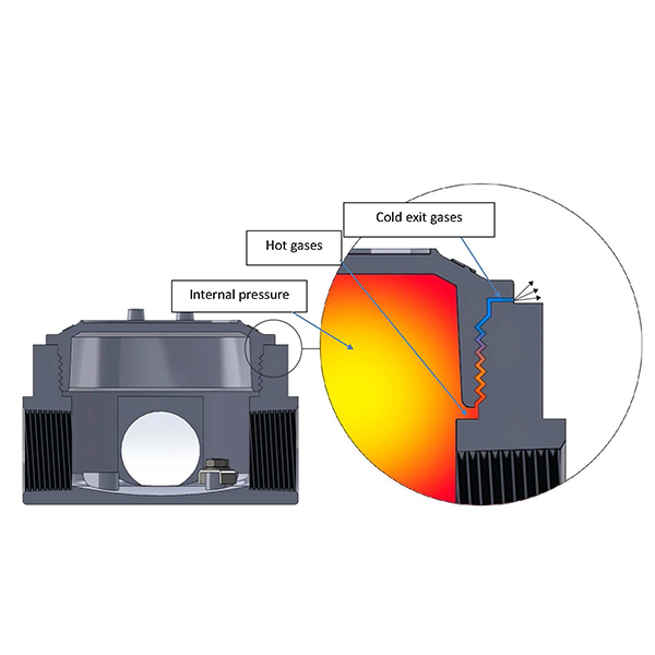
The basic concept of the 'Ex d' type of protection is that an explosion inside the explosion-proof device can occur but is contained without triggering the external gases. The function of the flame-proof joint is to ensure that the residual gases of the explosion are unable to ignite the atmosphere outside the flameproof enclosure.
As shown in figure 5 here below, the explosion produces hot gases inside the explosion proof enclosure. The resulting hot gas jets expand through the lamination joints and their temperature decreases considerably. During this passage, in fact, the energy released by the explosion is converted into the kinetic energy of the outgoing gases. [3]
For this process to take place as intended, the lengths and tolerances of the joints must be well determined as well as the surface roughness. The IEC/EN 60079-1 standard reports specific tables for this purpose.
In flanged joints such as those in Figure 5, the flue gases escape for a certain distance from the flat surface of the flange, thus being able to meet rigid obstacles on their path such as support structures, walls, pipes, etc. This fact has been incorporated into the plant engineering legislation with the imposition of a minimum distance between a flat flanged joint and a rigid obstacle depending on the group of GAS present at the installation site (Table 1).
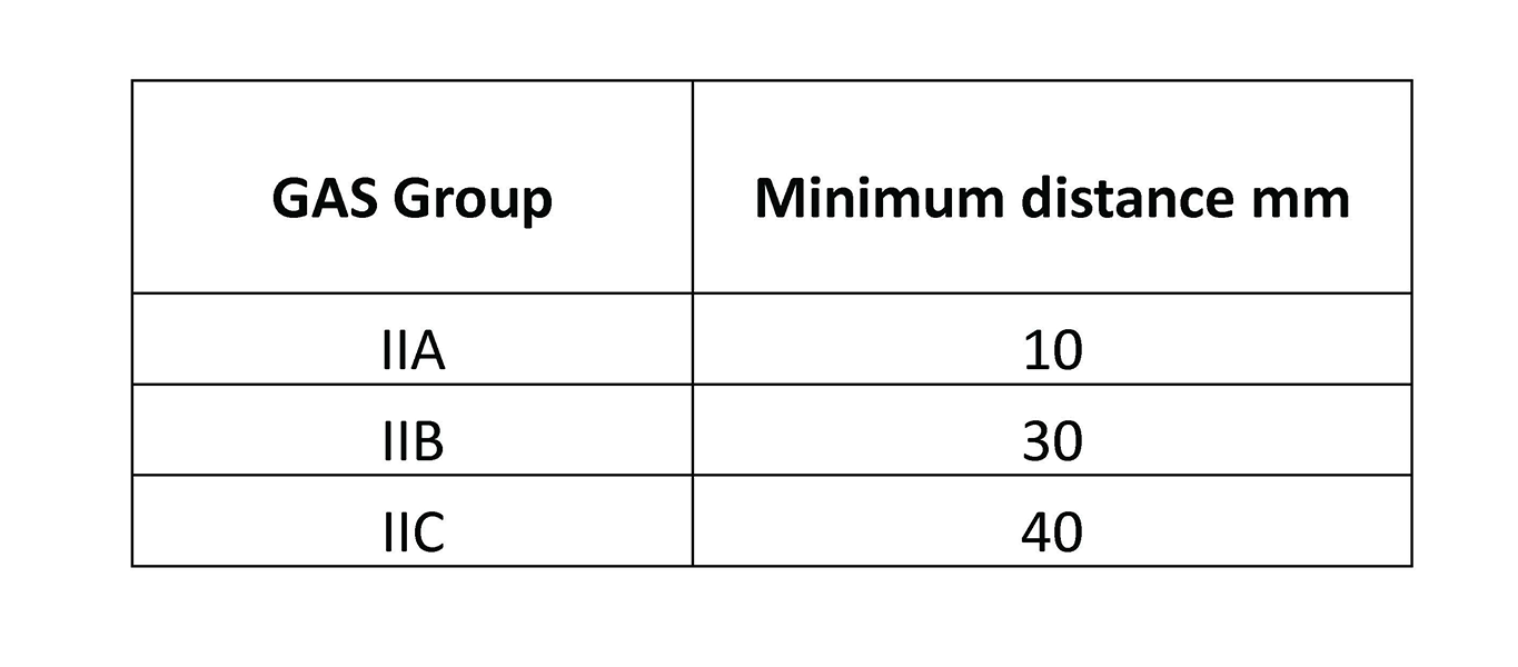
Table 1: minimum distance between flat joint and rigid obstacles according to the GAS group [4]
Another aspect that should not be underestimated is the tightening torque of the fixing screws of the flanged covers or cylindrical joints. These screws must be tightened with the correct torque indicated by the manufacturer in the use and maintenance manual. In fact, when the explosion occurs, the gases escape from all the paths or openings present and the interstices change because of the strong pressures that are exerted on the walls of the enclosure, increasing the passage opening through which the gases escape, as graphically represented in the Figure 6. [5]
On the other hand, when lids or elements with threaded lamination joints are present, the gas path develops in the spiral of their threading, in this case it is mandatory that the component is fully tightened ensuring at least five threads in contact.
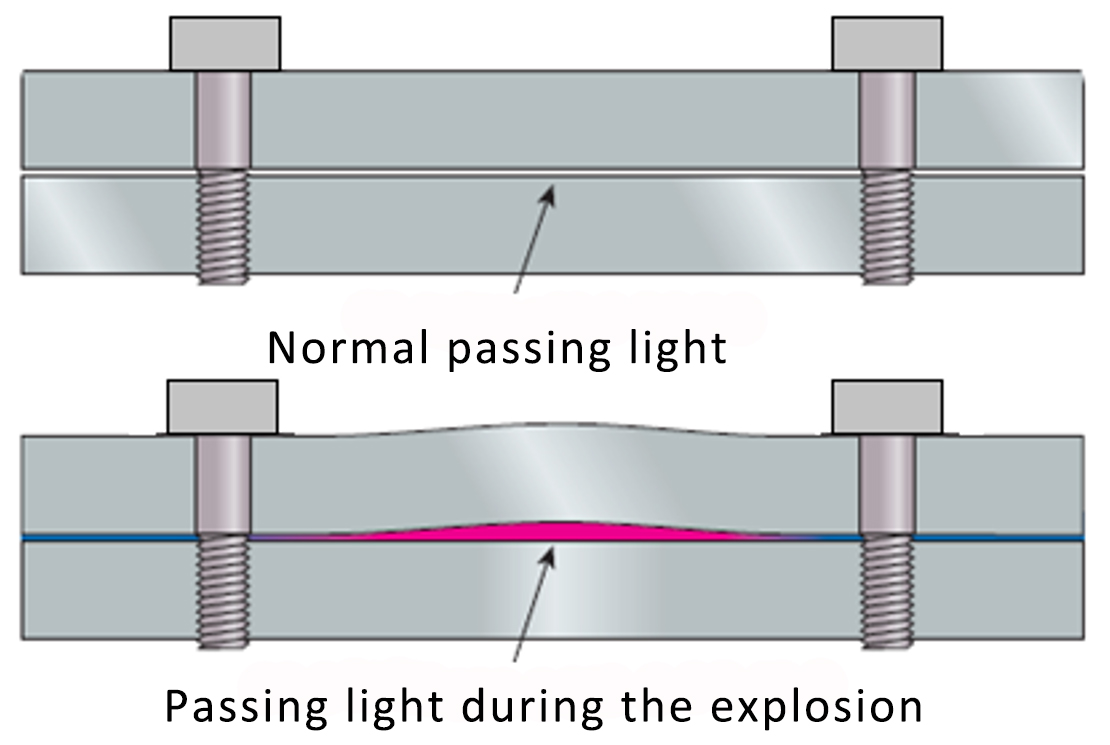
Figure 6: plane joint during the explosion
The protection of lamination joints
During maintenance operations to clean the flanged flat joints, non-metallic brushes and non-corroding cleaning liquids must be used. [6]
The use of grease for various purposes is envisaged and encouraged by the legislation on the joints. The use of grease during the assembly phase can prevent seizure in the cylindrical joints and in the threaded joints, facilitating the coupling, as they are always made with tight gaps. During assembly or maintenance, petroleum jelly or soap thickened with mineral oils can be applied to the joint surfaces to protect against corrosion.
Usually, the manufacturer's documentation comes in handy when choosing the detergent and grease. If there are no indications in this regard, the grease, if applied, must be of a type that does not harden due to aging, free of evaporating solvents and non-corrosive of the joint faces. [7]
Conclusions
Explosion-proof joints are a basic aspect of the protection offered by an explosion-proof equipment or enclosure. For this reason, understanding their function is a prerequisite for correct use and proper maintenance of all electrical devices that adopt this type of protection.
Notes and bibliographic references
[1] in addition to the three types of joints mentioned there are: conical joints, joints with partial cylindrical surfaces, labyrinth joints, serrated joints, and multi-section joints. In this article we consider those most used.
[2] see the article: The evolution of explosion-proof couplings 2017
[3] it has been observed that the type of material of the enclosure does not affect the decrease in the temperature of the outgoing gases, it is therefore wrong to think that the residual gases give heat to the enclosure. The decrease in temperature occurs due to phenomena like those of a rocket nozzle. Explosion protection - Heinrich Groh 2004 6.8.1 pag. 236
[4] CEI EN 60079-14 - Table 13
[5] NEC: National Electrical Code Handbook 501.3
[6] CEI EN 60079-17: 2015-03 par. 5.1
[7] CEI EN 60079-14: 2015-04 par. 14.3