The method of protection ‘Ex d’: general aspects
The 'Ex d' type of protection, now referred to as 'Ex db', is based on a simple theoretical concept: containment by means of a sturdy casing and flame retardancy. Its success is due to this simplicity, it is in fact one of the first methods of protection developed in the mining industry and still today it is one of the most widespread in areas classified for potentially explosive atmospheres.
by Andrea Battauz, R&D Project Engineer of Cortem Group
Introduction
In areas classified as at risk due to the presence of explosive atmospheres, the 'Ex d' type of protection is one of the most used types of protection and its application, over time, has proven to be versatile, effective, and long-lasting.
In Italy, devices with this type of protection are called explosion-proof [1] while in the Anglo-Saxon world they are defined as flame-proof to differentiate equipment compliant with European regulations from explosion-proof equipment according to American NEC 500 [2].
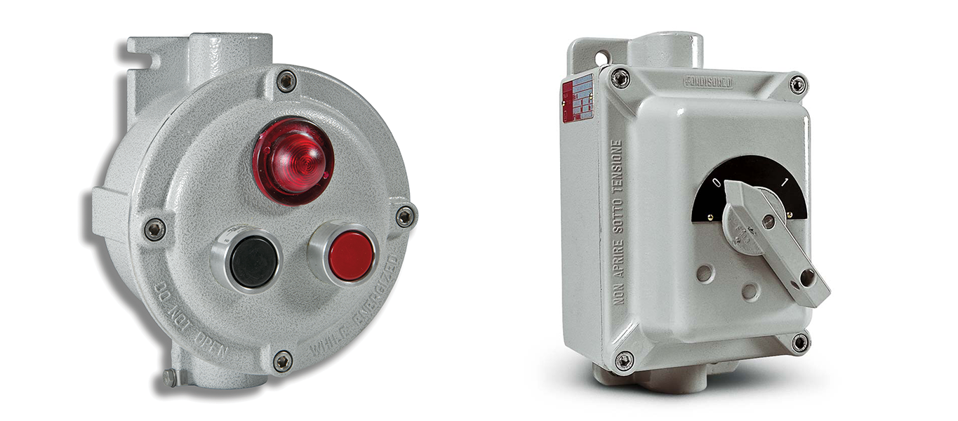
Figure 1: A switch and a push-button control station made according to the 'Ex d' protection method
In the international IECEx scheme and in the European ATEX standard, the 'Ex d' protection method has the IEC 60079-1 and EN 60079-1 standards respectively. In this regulatory framework, the seventh edition of IEC 60079-1 sanctioned the introduction of the 'Ex db' marking for devices with EPL Gb and 'Ex d' protection method. This coincides with the introduction of the additional levels 'Ex da Ga' and 'Ex dc Gc' for specific devices which are still quite marginal.
For simplicity in this article, we will indicate 'Ex db' with 'Ex d' meaning to restrict the field of discussion always and only to the EPL Gb.
The 'Ex d' protection method: the basic concept
The widespread use of explosion-proof devices has its roots in the basic principle of the 'Ex d' type of protection.
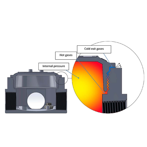
We could summarise this basic principle by saying that, should the explosion occur, it would be contained within enclosures without spreading to the surrounding atmosphere.
We therefore understand how the 'Ex d' type of protection represents a pragmatic response to the presence of an explosive atmosphere, even more important if placed in relation to the practical impossibility of creating complex electrical systems that are sealed with respect to the gases present in the surrounding atmosphere. [3]
A direct consequence of accepting that an explosion can occur inside an explosion-proof enclosure is the possibility of installing components inside it that contain ignition sources. By way of example only, the following are installed in the 'Ex d' enclosures: relays, changeover switches, rotating unions, contactors, automatic switches, and many other devices which, like these, can produce arcs in their normal operation, sparks, or other sources of ignition.
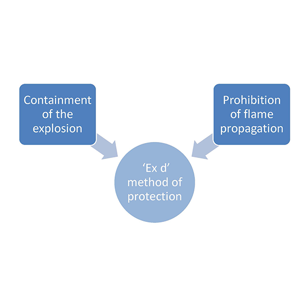
In Figure 2 the scheme of the basic principles of the 'Ex d' type of protection
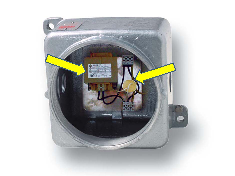
These “industrial standard” devices [4] placed inside explosion-proof enclosures and certified by a notified body obtain an EPL protection level equal to Gb and can thus be installed in Zone 1.
In figure 3 indicated with arrows, some examples of industrial standard devices in an 'Ex d' enclosure.
The containment of the explosion
The chemical reaction that generates the explosion owes its dangerousness to the pressures it exerts on the surfaces encountered in its expansion. These pressures fall most of the time in a range between 7 and 14 bars, varying from the lowest values of the Group IIA gases to the highest values of the Group IIC gases. For each device that is certified by a notified body, the pressure value that can be created inside it during the explosion is determined by means of a specific test to determine the reference pressure. This test recreates the worst case in which the explosion can occur, using different gas mixtures depending on the gas group of the appliance and gas/air mixtures with proportions indicated by the legislation.
Based on the reference pressure thus obtained, the housing of the explosion-proof device must then pass an overpressure test in which water is pumped into it at a pressure equal to 1.5 times the reference pressure. [5]
All this gives some idea of why the outer casing of an explosion-proof enclosure is therefore very robust. The metal walls of a device with 'Ex d' protection mode, whether obtained by casting or from welded carpentry, have considerable thicknesses, as well as the glass parts of the lighting equipment or the so-called glass "windows" of the enclosures. Another visible detail, an indication of this robustness, is the number and quality of the fastening screws.
It goes without saying that most explosion-proof devices are made of metal, preferring the manufacturing technologies from fusion, welded carpentry or directly from the processing of semi-finished products if the production lots were limited. Plastic materials are not completely excluded as they find application in small-sized devices, on which the pressures reported above are translated into negligible forces (F = P * S where P is the pressure and S the surface).
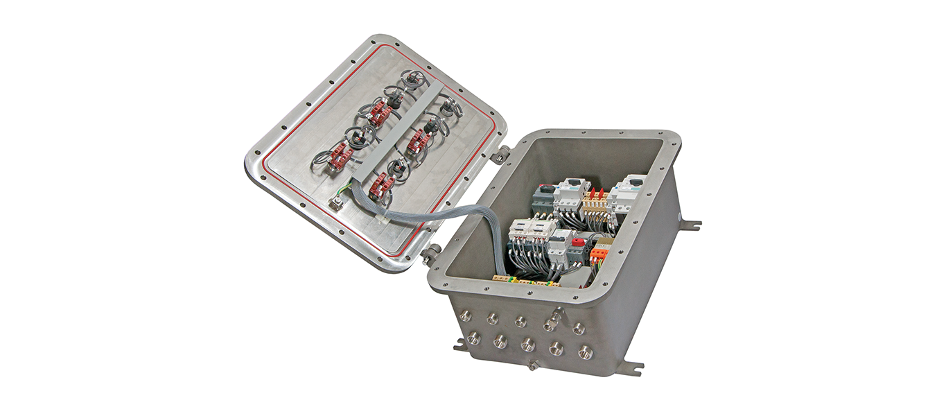
In figure 4 the massive appearance of a typical explosion-proof enclosure EJBX series
The non-propagation of the flame
The explosion-proof flame paths
Another feature of the 'Ex d' type of protection is the presence of explosion-proof flame paths. They correspond to the contact surfaces between two parts of an enclosure and have constructional features that prevent the propagation of an explosion inside the enclosure to the surrounding explosive atmosphere. [6].
To get an idea of their shape, the most common are the contact surfaces of the flanges between the body and the cover, the threads of the threaded covers and the cylindrical surfaces of the cylindrical joints.When the explosion occurs, hot gases are produced inside the enclosure, the resulting gas jets expand through the flame paths and their temperature decreases. At that point these residual gases are unable to ignite the gases external to the explosion-proof enclosure. [7]
In figure 5 an example of GAS lamination in a threaded joint.
To ensure that this process takes place in the expected manner, the lengths and tolerances of the joints must be well determined as well as their surface roughness. The IEC/EN 60079-1 standard reports specific tables for this purpose.
During the certification phase at the notified body, a specific non-transmission test of an internal ignition (often called flame non-transmission test) is simulated by realizing an explosion inside the explosion-proof device placed in a test chamber also filled with the same flammable gas. This test chamber is often made by wrapping the device in a transparent nylon bag specially filled with gas. The test result is considered satisfactory if the ignition is not transmitted to the test chamber. [10]
Cable inputs and conductors
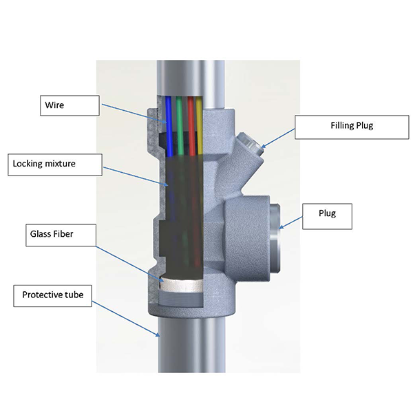
To avoid the propagation of the explosion, particular attention must be paid to the cable or conductor entries in explosion-proof enclosures or equipment.In this regard, it should be noted that in sites classified as being at risk of explosive atmospheres, systems with electrical conduits in a metal protective tube (conduit) are widespread.
Alternatively, we find systems with cable, more like to standard industrial systems.
In the presence of a conduit system, the inlets of the pipes in the enclosures must be made with locking joints, i.e., small containers, threaded at the inlet and outlet, inside which a specific sealing resin is poured (called a mixture of blockage or in some cases cement [9]).
The resin closes the interstices between one conductor and another, preventing a possible explosion from spreading from one case to another.
In figure 6 an example of a locking joint in a pipe system.
In the case of entry into the enclosure in a system with electrical cable conduits, except in rare cases, the entry into the enclosure is carried out via a cable gland. The cable gland must also be in 'Ex d' explosion-proof method of protection and be able to block a possible explosion. To guarantee this functionality, the choice of the cable gland must follow a precise selection criterion identified in the plant engineering standard EN/IEC 60079-14.
Conclusions
The 'Ex d' type of protection, now referred to as 'Ex db', is based on a simple theoretical concept: containment by means of a sturdy casing and flame retardancy. Its success is due to this simplicity, it is in fact one of the first methods of protection developed in the mining industry and still today it is one of the most widespread in areas classified for potentially explosive atmospheres.
An explosion-proof device, if used with due care, is effective and long-lasting.
Knowing its main characteristics is however necessary to build systems that maintain their extraordinary degree of safety.
Notes and bibliographic references
[1] CEI EN 60079-1: 2016-3.1
[2] National Electrical Code Handbook 2011 - Definitions PAG. 26
[3] This is due to the phenomenon of breathing that occurs in correspondence with the heating and cooling cycles of electrical devices, a consequence of electrical switching on and off. In each cycle, a depression is produced in the cooling phase which sucks up the external atmosphere.
[4] IEC 60079-0 Ed.7 6.1b
[5] This level of the safety factor equals to 1.5 provides for the execution of a test routine in production, which can be avoided by increasing the coefficient from 1.5 to 4.
[6] CEI EN 60079-1: 2016-03 3.3
[7] Explosion protection - Heinrich Groh 2004 6.8.1 page 231
[8] CEI EN 60079-1: 2016 11.3.2, 11.3.3 [9] The term cement derives from the first compounds used; powders like cement recently replaced by more performing bi-component resins