Accessories for connecting flameproof motors
Increased safety electric motors or flameproof electric motors with increased safety connection box have been on the market for many years. Let's see the connection of Ex- db electric motors with Ex- db connection box to the power line by using some examples of system applications
by Andrea Battauz, R&D Manager of Cortem Group
Premise
Increased safety electric motors or flameproof electric motors with increased safety connection box, which facilitate the connection of this equipment to the power line, have been on the market for many years. These very common motors are often chosen by many designers.
In this article we will delve into the connection of Ex- db electric motors with Ex- db connection box to the power line using electrical connection accessories, such as adapters, conduit sealing fittings, cable glands and flexible tubes.
In this regard we will give some examples of system applications, remembering that the choice of these accessories, as is the case for cables, is the responsibility of the designer who must scrupulously apply what is foreseen by applicable edition of the IEC/EN 60079-141.
Connection to a conduit system
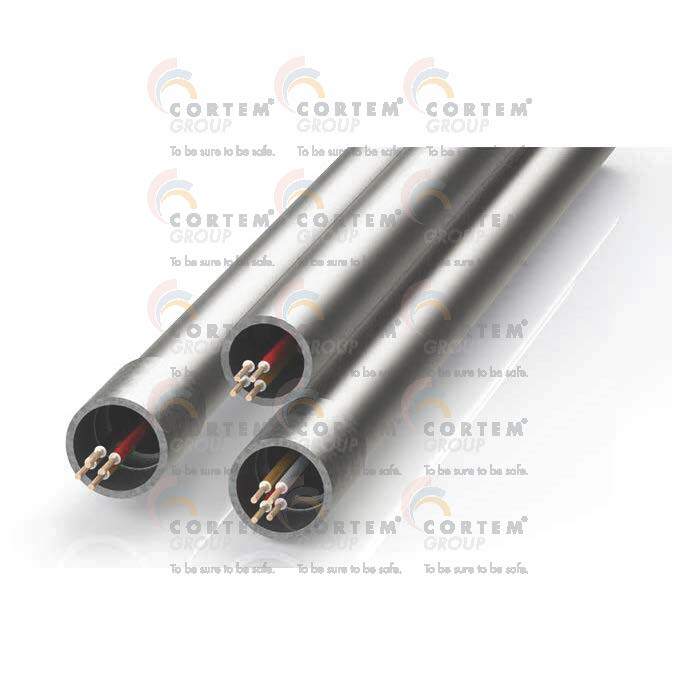
In sites classified as at risk of the presence of explosive atmospheres, systems with metal protective tubes, commonly known as conduit system, are very common. Single insulated wires are usually laid inside these pipes, as in Figure 1 here on the left.2
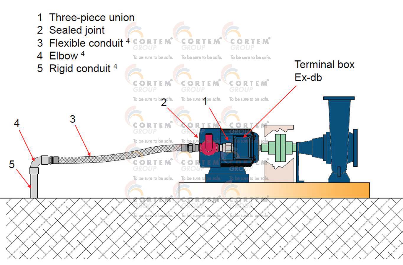
Figure 2: Exampleof connection between a flameprrof motor and a conduit system
In figure 2, we see the connection of amotor with an flameproof connection box. To prevent a possible explosion inside the flameproof equipment from spreading to the system, a conduit sealing devise was used3. Another important connecting element is the three-piece unions. This adapter can be used to give the right inclination to the sealing fittings, necessary for pouring and filling resin inside. Finally, the connection with the system in metal ducts is made with a flexible tube which, while maintaining high mechanical protection, allows the transmission of vibrations produced by the machine in operation to be reduced. It is a good rule to prevent any vibrations produced by the machine from being transmitted to the pipes and boxes of the conduit system, therefore the connection to the machine must be carried out with flexible tubes with a metal core with mechanical characteristics equivalent to those of rigid tubes4.
Connection to a cable system
If the system to which the machine is connected has visible cable laying, the entry into the connection box with cable glands must be made by applying the selection criterion of the latest edition of EN 60079-14. The main discriminant introduced by this selection criterion is the type of cable; in fact, the solid filling material5 between the individual conductors of a multi-core cable must not allow the flame to pass in the event of an explosion and, at the same time, must deform without being crushed by the pressure action exerted by the cable gland rubber.
When a cable is not equipped with these characteristics, a barrier type cable gland must be used. In this device the installer, after eliminating sheaths, screens and filler from the cable for a section, throws a two-component resin into a special bushing. This operation replaces the solid filler material between the individual single-core cables with resin, eliminating the gaps.
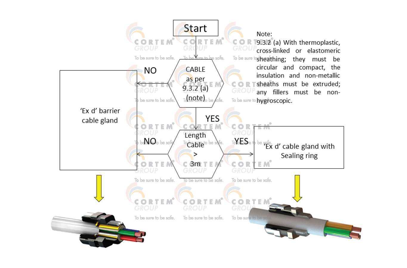
Figure 3 : Flow chart based on the EN 60079-14:2014-036
Figure 4 shows the connection of a vibrating machine using barrier cable glands. When, as in this case, the cable has a length of less than 3m or does not have a filling material as required by the standard, the use of the barrier cable gland is foreseen on both the motor and system sides.
Armored cable is often chosen in sections where the cable is exposed for greater protection from mechanical risks.
However, if the cable is sufficiently long (>3m) and meets the requirements of the standard7, a cable gland with rubber grommet can be used. Also in this case, it is advisable to use an armored cable to increase the level of mechanical protection of the cable8.
Figure 5 shows the connection: if, after a visible section, the cable continues in a metal protective tube, the cable is said to be laid in an open conduit system.
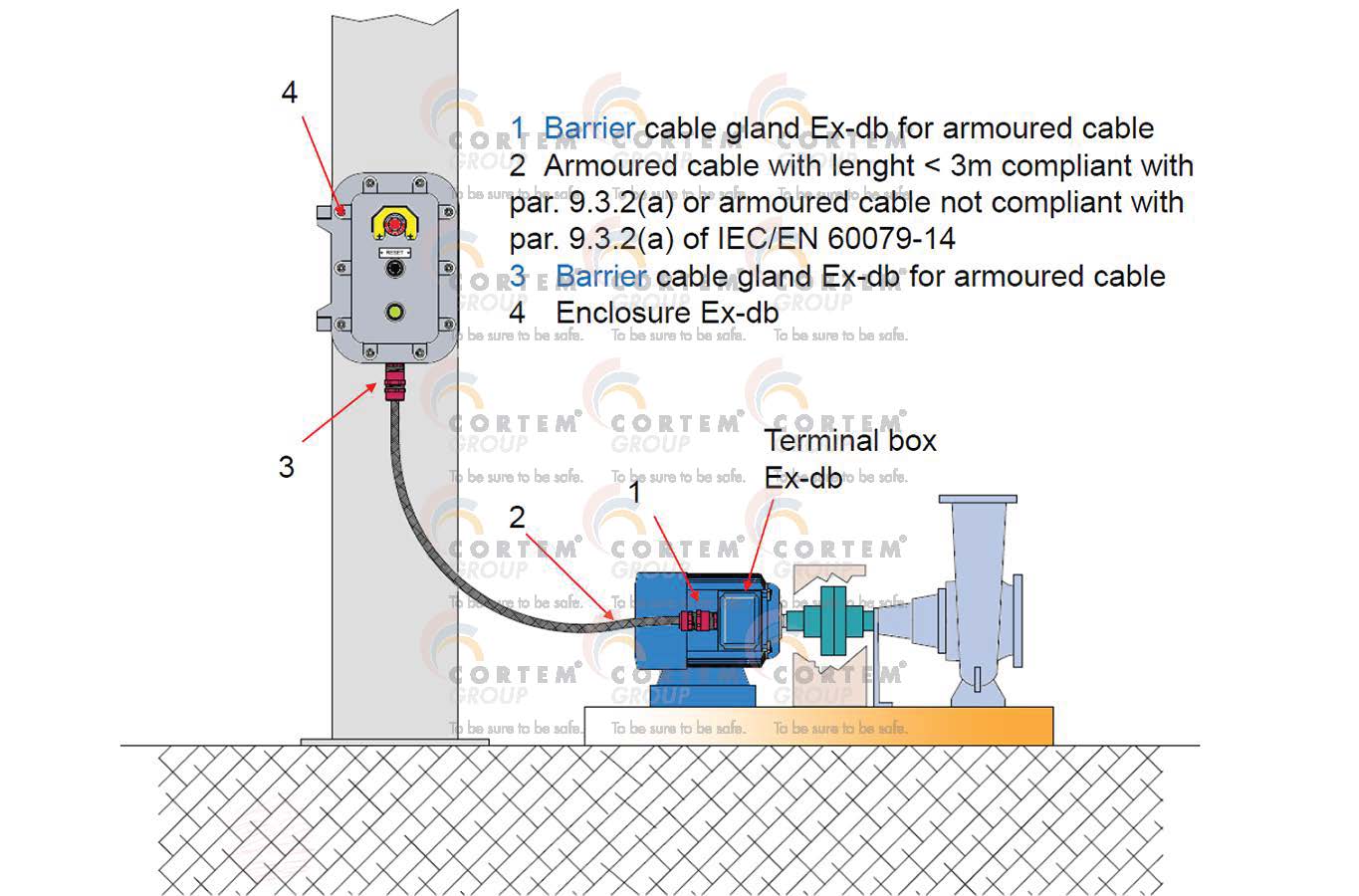
Figure 4 : Example of connection of a flamproof motor with barrier cable gland
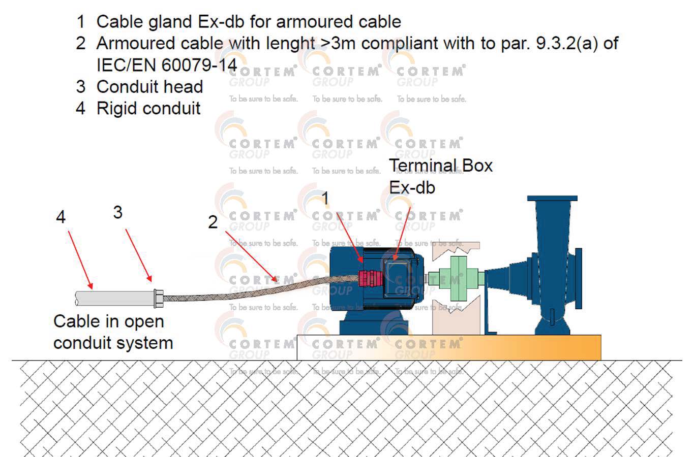
Figure 5 : Example of connection of a flameproof motor with cable gland with rubber
Conclusions
Motors completely made in flameproof protection are still widely used and very present in plants. They are imore and more accompanied by increased safety Ex- eb motors or Ex- db motors, with an enclosure with Ex- eb connection bos. In the next article we will delve into the connection of the motor connection box made with Ex-eb protection mode.
1 - par. 10.6.2
2 - See “The ‘Ex d’ protection method: electrical conductors in metallic protective tube” – Cortem Group News 05/27/2022
3 - The conduit sealing device the system into an equipment side, where Ex equipment and/or components are mounted, and a system side where line accessories consistent with EN 60079-14 and relevant national legislation are required, see CEI 31-108 9.4.1
4 - Extract of the CEI 64-2 standard, page 86 6.1.01 (8) now replaced by CEI EN 60079-14, in the latter there are no prescriptions in this regard. However, this excerpt still makes absolute common sense.
5 - CEI 31-108 Fig. 10.6-B
6 - See “The 'Ex d' protection method electrical cable installation and cable gland selection criteria” - Cortem Group News 09/28/2023
7 - EN 60079-14 9.3.2 (A) or better explained in the guide CEI 31-108 9.3.2 (A)
8 - For the choice of armored cable, please refer to the article “The 'Ex d' type of protection: electrical cable installation” - Cortem Group News 06/21/2022