The evolution of the Ex-proof flame path
As written in previous dissertation, the most critical part of a flameproof enclosure 'Ex d' is the flame path. Although the Standards are...
As written in previous dissertation, the most critical part of a flameproof enclosure 'Ex d' is the flame path.
Although the Standards are divided into National standards (CEI EN 60079- ...), Community standards (EN 60079- ...) and international standards (IEC 60079- ...), which in fact are the same, we will quote below only the reference 60079- ...
The reference standard, 60079-1 "Explosive atmospheres Part 1: Equipment protected by explosion proof enclosures ‘d’, has been updated so that in this discussion we will analyse the changes relating to the use of the flame path.
This is the oldest method of protection that exists, the first used and still one of the safest because it is based on a very simple technology and, therefore, hardly fallible.
This method, designed for protection in systems where may be an explosive atmosphere in form of gas, is based on the assumption that it’s impossible to prevent a gas to penetrate everywhere. No gasket will ever be able to prevent the entry of a gas in an enclosure. Therefore, if an explosive atmosphere penetrates into an enclosure producing a trigger, for example a spark between two electrical contacts, the explosion occurs, but it remains confined within the enclosure and does not allow the spread of flame to the surrounding atmosphere, thus causing a devastating explosion.
To ensure this, enclosures must be constructed with a mechanical strength such as to contain the overpressure caused by the explosion and to allow the escape of flue gases. This is the mission of the flame path which is the interface between two parts of an enclosure, for example the body and the lid. It allows the gases to exit the enclosure and to cool down during the passage, so that they are no longer able to trigger the outside atmosphere. For this reason, the flame path must be sufficiently long and with an interstice enough narrow to guarantee the cooling of the flue gases.
Flame path, whether of permanent closed type or of the type intended to be opened occasionally for operation and/or maintenance operations, must meet, in the absence of pressure, the requirements of standard 60079-1 standard and considering that that they have to be sized to support the mechanical effort resulting from the internal deflagration phase.
The flame path may be of different types, depending on the nature of the gas and the volume of the housing and, consequently, they will have a size and shape depending on the type of gas present in the environment of installation of the explosion-proof equipment.
To better exemplify how many and which types of flame paths are provided for the Standard 60079-1, we will give a brief description, considering the limitation of their use in accordance with what prescribed in Tables 2 and 3 of this Standard, which for convenience we report here below.
Table 2: Minimum width of the flame path and maximum gap for enclosures of Group I, IIA and IIB
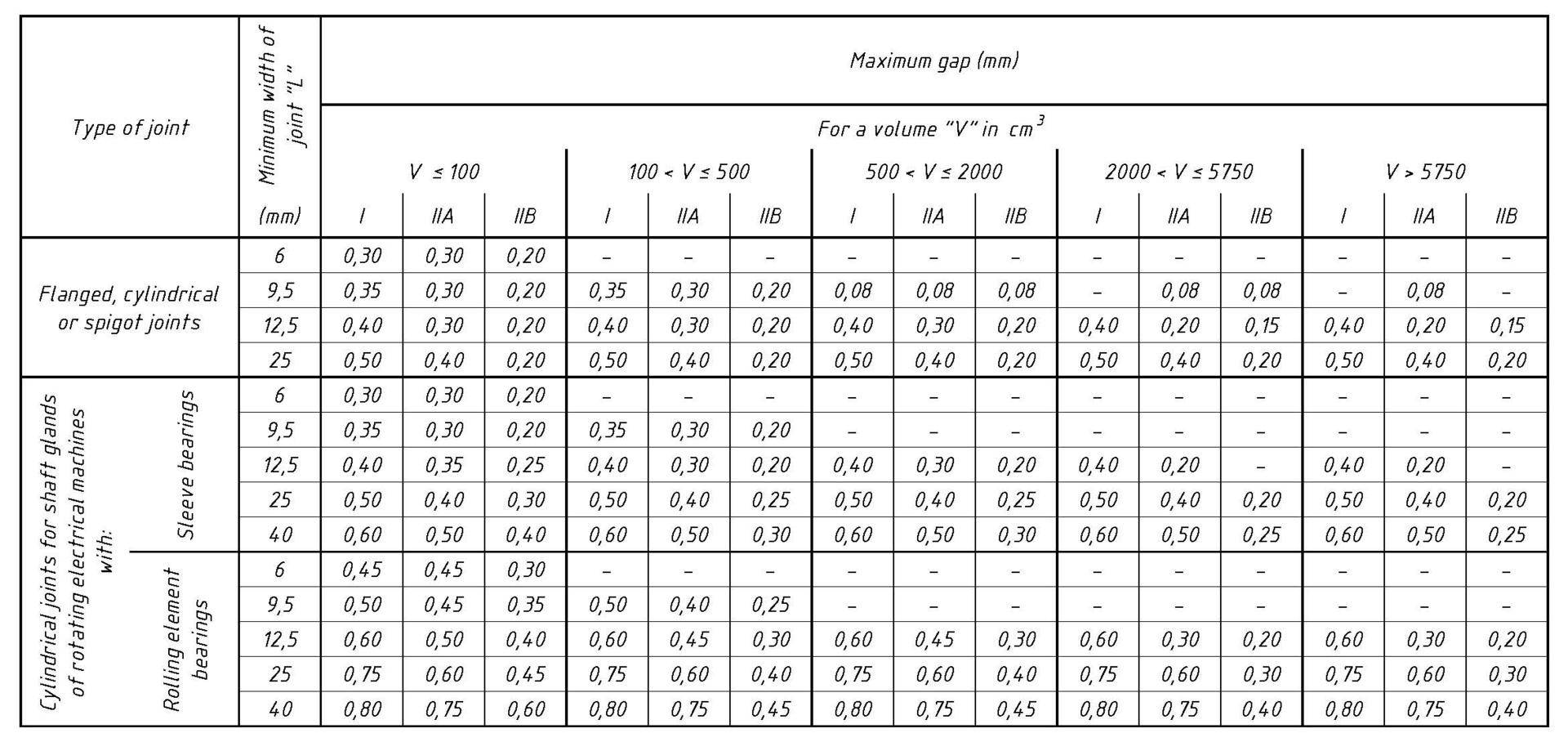
Note 1: for the determination of the maximum distance, the constructive values must be rounded in accordance with ISO 80000-1 (3) Standard.
Note 2: in this edition of 60079-1 Standard, two new columns were introduced to divide the "V" volume. This subdivision has been made to introduce maximum dimensions of the gap for cylindrical flanged joints or spigot ones with a minimum length "L" of 9.5mm, as it was non-existent in the previous version of the standard. In particular, it has been introduced the "0:08" value for the group IIA and IIB, with "V" volume 2000
Note 3: these gap and volume maximum values associated, are based on historical US data, for Class I, Division 1, according to the documentation from ANSI/UL 1203 (4).
Table 3: Minimum width of the joint and maximum gap for enclosures of Group IIC

Note: for the determination of the maximum distance, the constructive values must be rounded in accordance with ISO 80000-1 Standard.
a. Flanged joint is permitted for explosive mixtures of acetylene and air only if they comply with para 5.2.7 of the standard 60079-1.
b. The maximum gap of the cylindrical portion is increased to 0.20 mm if "f" <0.5 mm
c. The maximum gap of the cylindrical portion is increased to 0.25 mm if "f" <0.5 mm
Now, we analyse the various types of flame path considered in the 60079-1 standard currently in force.
1. Threaded joints
Threaded joints shall be complying with the requirements of Tables 4 and 5 of 60079-1 standard. They are divided into two types such as:
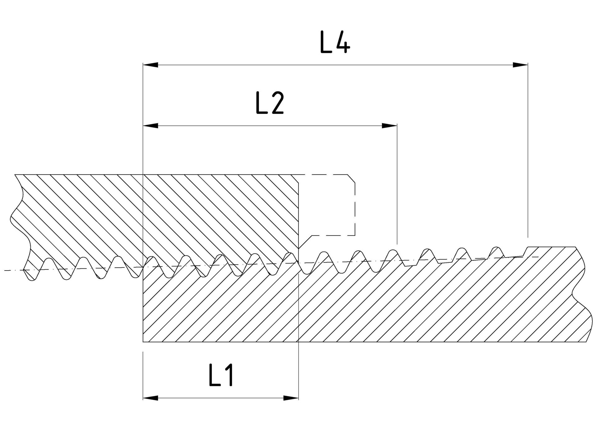
a. Cylindrical joints (refer to Table 4 of 60079-1 Standard), they must have a larger pitch than or equal to 0.7 mm, whereas if the step is greater than 2 mm, special precautions may be necessary as a greater number of full threads in order that these threads meet the test of non-transmission of an internal explosion, as prescribed in the tests of non-transmission of an internal ignition (see para 15.3 of the standard); furthermore, the shape of the thread and the quality of workmanship may have the average or fine tolerance, according to ISO 965-1 and ISO 965-3 standards or, if they do not comply with these standards other threads are allowed, in relation to the thread shape and the quality of processing, if it is exceeded the flame-proof test always prescribed in para 15.3 of the standard, when the length of the threaded joint is specified by the manufacturer; It is reduced as specified in Table 9 of the Standard; they must have at least 5 full threads; they must have a length of thread greater or equal to 5mm for volume less than or equal to 100 cm3 or greater than or equal to 8 mm for volume higher to 100 cm3.
b. Tapered joints (refer to Table 5 of 60079-1 Standard), they must have at least 5 threads of the same size, both on the external and internal side; thread must meet the NPT requirements, according to ANSI/ASME B1.20.1 and must ensure a firm coupling; accessories with male thread with an edge or an thread interruption must be provided with an effective length of the thread not less than the "L2" and a length dimension of not less than "L4" between the face of the edge and the end of the accessory thread; the internal threads must be controlled using a buffer calibre, for the verification of the L1 measurement.

2. Non-threaded joints
The non-threaded joints shall be complying with the requirements of Tables 2 and 3 of the 60079-1 standard, reported above and they consist of:
a. Spigot joints. For the determination of the "L" width of spigot joints, one of the following shall be taken into account:
- both the cylindrical part and the plane part. In this case, the gap shall nowhere exceed the maximum values shown in Tables 2 and 3 (see Figure 1a)
- the cylindrical part only (see Figure 1b). In this case, the plane part need not to comply with the requirements of Table 2 and 3.
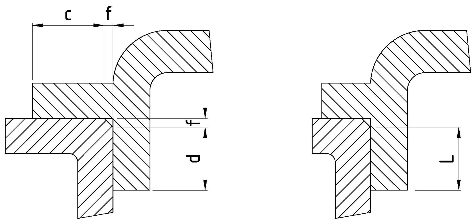
Figure 1a: Cylindrical part and plane part
Figure 1b: Cylindrical part only
Key
L= c + d (I, IIA IIB, IIC)
d ≥ 0.50 L (IIC)
c ≥ 6.0 mm (IIC)
≥ 3.0 mm (i, IIA, IIB)
f ≤ 1.0 mm (I, IIA, IIB, IIC)
b. Conical joints. When joints include conical surfaces, the width of the joint and the gap perpendicular to the joint surface shall comply with the relevant values of Table 2 and Table 3 above. The gap shall be uniform through the conical part. For electrical equipment of Group IIC, the cone angle shall not exceed 5°.
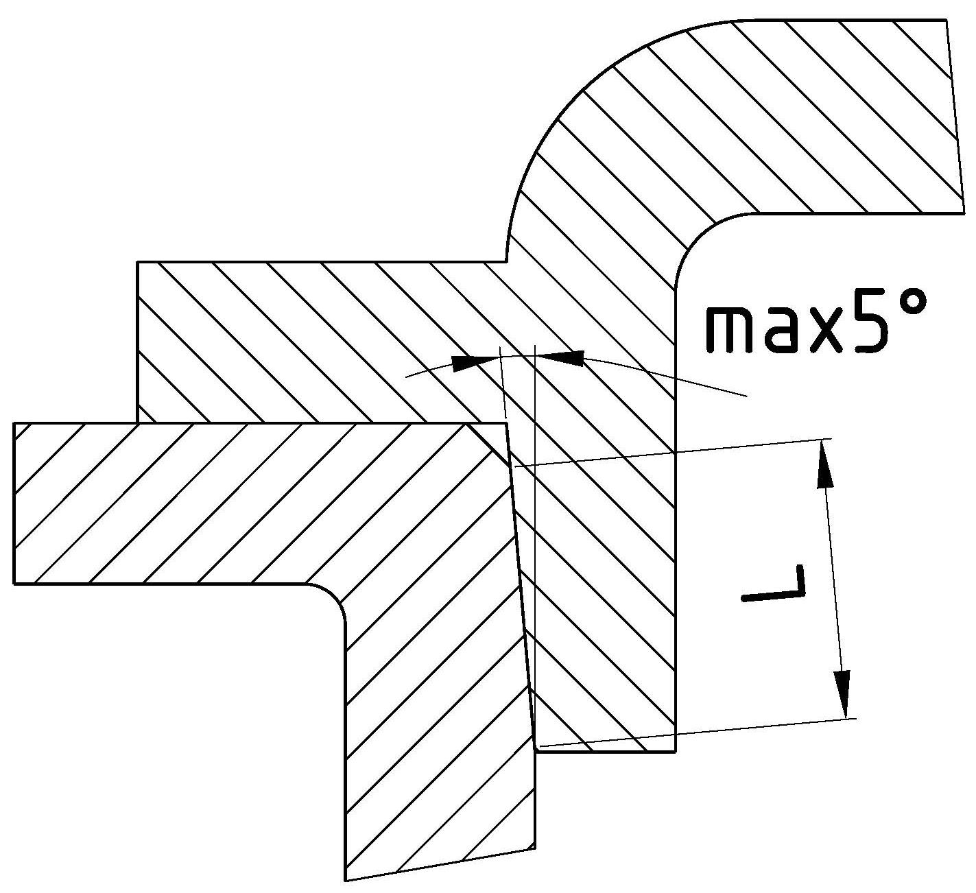
Note: The cone angle is the angle between the major axis of the cone and the surface of the cone.
c. Joints with partial cylindrical surfaces (not permitted for Group IIC). There shall not be intentional gap between the two parts. The width of the joint shall comply with the requirements of the Table 2 above.
The diameters of the cylindrical surfaces of the two parts forming the flameproof joint and their tolerances shall ensure the compliance with the relevant requirements for the gap of a cylindrical joint as per Table 2 above.
d. Flanged joints for acetylene atmospheres. Flanged joints are permitted for electrical equipment of Group IIC intended for use in explosive gas atmospheres containing acetylene providing all the condition required at the paragraph 5.2.7 of the 60079-1 Standard (gap I: ≤ 0.04mm; width L ≥ 9.5 mm and volume ≤ 500 cm3).
e. Serrated joints. They don’t need to comply with the requirements of Table 2 and table 3 above but shall have at least five full threads, a pitch greater than or equal to 1.25 mm and an included angle of 60° (± 5°). This serrated joints shall only be used for joints that are fixed during operation.
Serrated joints shall satisfy the test requirements of 15.3 of the 60079-1 Standard.
Key
Y ≥ 5 T
Test length: Y/1.5
T ≥ 1.25 mm
α = 60° (± 5°)
f. Multi-step joints. They consist of not less than 3 adjacent segments where the path changes direction not less than two times by 90° ± 5°.
Multi-step joint doesn’t need to comply with the requirements of Table 2 or Table 3 above, but shall satisfy the test requirements of 15.3 of 60079-1 Standard, with the test length of each segment reduced to not more than 75% of the manufacturer’s specified minimum length.
For flameproof enclosures that incorporate multi-step joints, the equipment certificate number shall include the “X” suffix in accordance with the marking requirements of 60079-0 Standard and the specific conditions of use listed on the certificate shall detail one of the following:
- Dimensions of the flameproof joints shall be detailed; or
- Specific drawing with details of the dimensions of the flameproof joints; or
- Specific guidance on how to contact the original manufacturer for information about the dimensions of the flameproof joints; or
- Specific indication that the flameproof joints can’t be repaired.
Key
H = 3 adjacent elements
α= 90° ± 5°
3. Holes in joint surfaces
Where a plane joint or the plane part or a partial cylindrical surface of a joint is interrupted by holes intended for the passage of threaded parts for the assembling of a flameproof enclosure, the distance “l” to the edge of the hole shall be equal to or greater than 6 mm when the width of joint “L” is less than 12.5mm; 8 mm when the width of joint “L” is equal to or greater than 12.5 mm but less than 25 mm; 9 mm when the width of joint “L” is equal to or greater than 25 mm.
The distance “l” is determined as follows.
- Flanged joints with holes outside the enclosure

Figure 3
Figure 4
The distance “l” is measured between each hole and the inside of the enclosure
- Flanged joints with holes inside the enclosure
Figure 5
The distance “l” is measured between each hole and the outside of the enclosure
- Spigot joints in which to the edges of the holes, the joint consist of a cylindrical part and a plane part.
Figure 6
The distance “l” is defined as the sum of the width “a” of the cylindrical part and the width “b” of the plane part, if “f” is less than or equal to 1 mm and if the gap of the cylindrical part is less than or equal to 0.2 mm for electrical equipment of Groups I and IIA, or 0.15 mm for electrical equipment of Group IIB, or 0.1 mm for electrical equipment of Group IIC (reduced gap) or the width “b” of the plane part alone, if either of the above mentioned conditions are not met.
- Spigot joints where, to the edges of the holes, the joint consist of the plane part, in spite of plane joints are permitted (see paragraph 5.2.7 of 60079-1 Standard).

Figure 7
Figure 8
The distance “l” is the width of the plane part between the inside of the enclosure and a hole, when the hole is outside the enclosure (Figure 7), or between a hole and the outside of the enclosure where the hole is inside the enclosure (Figure 8).
4. Flame paths on rotating machines
On ‘Ex d’ rotating electrical machines, it’s necessary to provide a flame path on the propeller shaft. Flame paths positioned in such places must not be subject to wear. They must be completely free and independent from the other structures that support the propeller shaft allowing the rotation. Any bearings, seals, lubrication channels, etc. must be outside of the length of the flame path and it must not be interrupt.
5. Gaskets (including O-rings)
6. Roughness
The surfaces of joints shall be such that their average roughness “Ra” does not exceed 6,3 µm.
Note: average roughness is derived from ISO 468. Determination can be made by visual comparison to a reference plate. Today the flame path surfaces, thanks to machining carried out by modern machine tools with numerical control, reach degrees of roughness enormously lower and, therefore, more safe.
7. Joints protected against corrosion
The surface of the flame path can be protected against corrosion but is not admitted their coating with paints or finishes based powder.
Other types of coatings can be used, if it is proved that the material used and the procedures to apply it does not adversely affect the coupling of flame path properties.
It is possible to apply an anti-corrosion grease before assembly. The fat, when applied, must be of type non-hardening with aging, it must not contain solvents which evaporate and must not cause corrosion of the joint surfaces and the verification of its suitability must be in accordance with the manufacturer's specifications fat.
We conclude recalling that to ensure the safety of the enclosure, it is appropriate to check that the flame paths are not obstructed and that they are not in close proximity to solid objects such as pipes, walls, trellises or even other enclosures, which may impede the proper exit of gases fuels. In this regard, please refer to the mounting and installation requirements contained in the 60079-14 standard.