The new EN 60079-14 Standard
The correct use of cable gland A few months ago was released the updated version of the European standard EN 60079-14 concerning the...
A few months ago was released the updated version of the European standard EN 60079-14 concerning the design, selection and installation of electrical systems for areas with potentially explosive atmosphere that has replaced the old version, which will remain in force until January, 1st 2017.
What distinguishes the new legislation respect to the previous version has been the elimination of the scheme for the selection of entries in Ex enclosures (Figure 1).
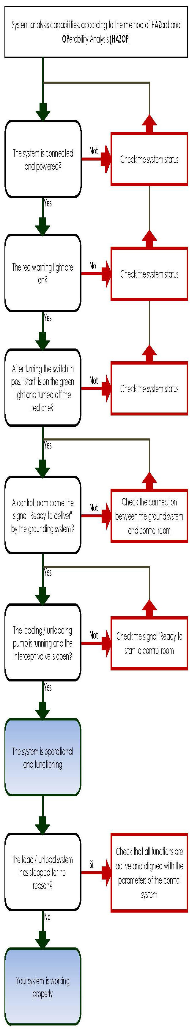
Figure 1 – The scheme eliminated from EN 60079-14 standard
1. Methodologies of entries in explosion-proof enclosures
The first version of EN 60079-14 Standard also, dating back to the late 90s, regulated the systems of cable entry in electrical apparatus.
The norm admitted some methods that have remained unchanged over time:
1. sealed cable glands (barrier cable glands);
2. standard Ex cable glands, with compression rings;
3. locking joints;
4. indirect entry (housing 'Ex d' tied to 'Ex e' housing with sealing bushings);
5. cable gland with MI cable plus metal sheath.
We have already spoken in previous article about locking joint. Now, it’s interesting to analyse the use of cable glands to enter directly in explosion-proof enclosures. These cable glands, following the 'Ex d' type of protection, meet the requirements of EN 60079-1 Standard and must be certified and marked.
They can be of different types, depending on the uses to which they are intended. Normally, they are of two mail categories:
• cable glands with compression ring (REV);
2. Cable glands with compression rings
The cable glands must be selected according to the diameter of the cable. The seal, in fact, is ensured by the compression of a rubber gasket that tightens on the outer diameter of the cable and does not allow the propagation of the flame outside the enclosure.
Normally, the sealing gasket has a length that corresponds to the maximum length of the flame-path; some cable glands, with shorter seal, can be used for housings with internal volumes limited by the certificate.
On the gaskets are indicated the minimum and maximum diameters of the cable use.
Is not allowed put more cables in the same cable gland and even increase the diameter of the outer sheath of the cable with the application of insulating tape or other means, to match the diameter of the gasket.
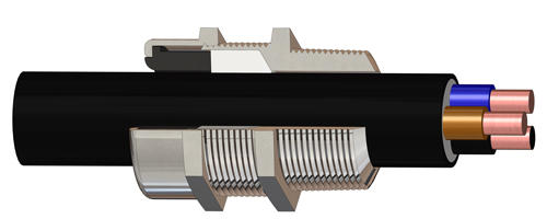
The cable glands for armoured cables have two seals, the first, anterior, is the one that seals on the inside diameter of the cable ensuring the explosion protection, the second, rear, seals on the outer sheath of the cable and protects against the entry of liquids into cable gland, where the armour is blocked by two conical rings that ensure the electrical continuity of the ground.
If you remove a cable, for the maintenance operations, it’s advisable to replace the seals because they could not be more reliable.
3. Barrier cable glands
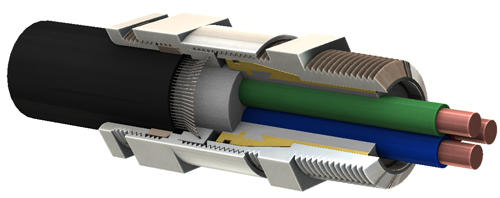
In barrier cable glands, the conductors of the cable are sealed by a resin in a sleeve which, when inserted into the gland, form a flame-path with the inner part of the body. In this case, during maintenance operations, the cable glands can be disassembled and reassembled without any problem, only by checking that the flame-path surfaces result intact.
Until now, these were the only cable glands authorized to be used for direct entry into enclosures that contain sparkling equipment, in IIC junction boxes and, when installed in Zone 1 also for enclosure with volume greater than 2 dm3.
4. What changes with the new version of the EN 60079-14 Standard
The previous versions of the Standard made an important distinction between the possible uses of cable gland with compression rings, compared to "barrier" cable glands that could be used in any type of hazard.
The new version of the standard does not cite any more volumes, the areas of installation or the note if there is or not sparkling material inside the junction boxes.
This, to a first surface analysis, could be assumed that any cable gland with compression rings will, henceforth, be used in replacement of the more secure "barrier" cable gland.
But this is not absolutely true. The Standard defines the precise limits for the use of cable glands with compression ring instead of the "barrier" cable glands:
- the cable glands must be certified as "equipment" (such as Cortem cable glands REV series);
- the cable gland cannot be certified as a "component" (U in the final marking of the certificate);
- cables must follow the requirements of EN 60079-14 (paragraph 9.3.2°);
- the length of the input cables must be at least of 3m.
It’s expected that this modification of the standard will implicate misunderstandings, in the near future, about the cable glands installation. The risk is that, an apparent simplification creates confusion especially in the designers and installers. We remind that it’s responsibility of the installer to carefully evaluate the type of plant and the choice of the type of cable gland to be used, barrier or with compression ring. Manufacturers like Cortem, unable to know the detailed design of the plant, can only raise the customer to carefully evaluate these aspects and quote the cable gland indicated by the customer during the RFP.