The plant normalization
Concepts of a proper sizing of equipment and electrical equipment for installation in potentially explosive atmospheres with the presence...
In this treatment we will discuss the concepts and the guidelines adopted for the proper plant design, the electrical plant dimensioning and the related equipment selection.
During the engineering construction and development stage, the electrical designer will be responsible to collect from all other disciplines, information on quantities, physical and orographic location of all electrical equipment to be powered and managed.
Except for specific plant requirements stated by customer requests, the sizing is planned analyzing the following variables:
- The distribution system
- The voltage levels
- The system of the neutral at the various levels of the distribution system
- The choice of equipment
- The load centers
- The capacity of the electrical system
- The voltage drop
The distribution system will be designed according to factors that may influence the choice such as continuity of operation, the degree of reliability of the power sources, the total load, the concentration of utilities, the operating costs, a feasible maintenance, etc…
The voltage levels will be chosen according to the entity and orographic dislocation of the loads to be supplied, the prediction of future expansion of the system, the power of short circuit values resulting in the various points of the system and the possibility of reducing to the minimum voltage levels, compatibly with the voltage drops.
Usually the system of the neutral, the LV side, is provided with the neutral point connected directly to ground, while the MV side, is provided with the neutral point connected to ground through a resistor adapted to limit the current of phase to earth fault, without affecting the functionality of the protections coordination.
The choice of equipment will be a function of the sizes resulting from the calculations of the power absorbed by the load and with the safety factors applicable, selecting such equipment in the range of standard sizes available on the market.
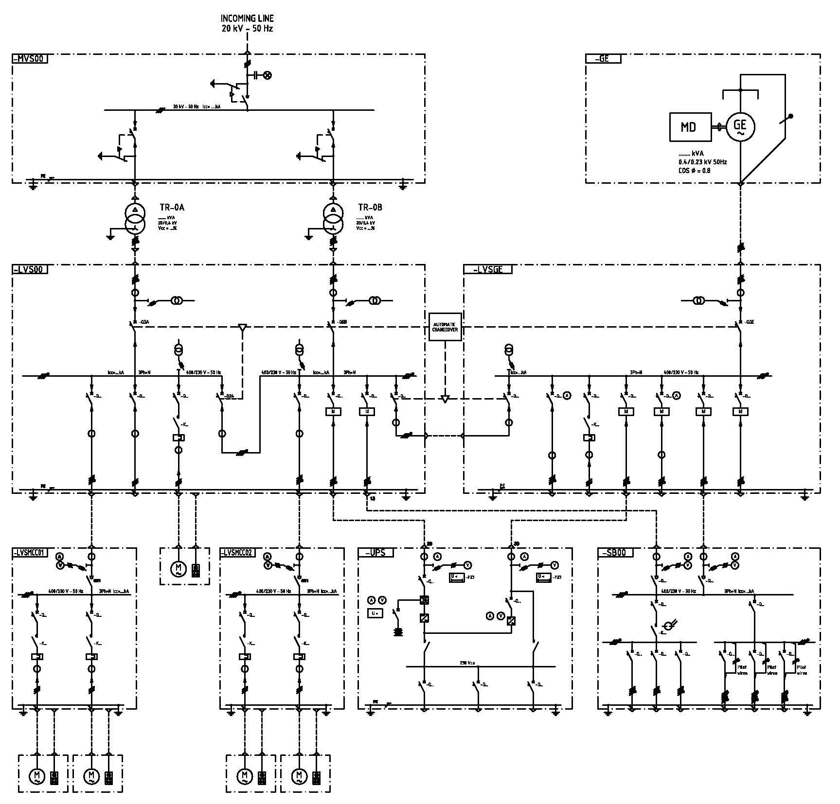
The load centers, independently from the configuration that will take on the distribution system, are normally divided into MV switchboards (MVS), distribution boards and starter (for motors above 30 kW) Low Voltage (LVS-Power Center), switchboard of starter motors (LVSMCC- Motor Control Center) Switchboard for auxiliary services (ASS), privileged switchboard, powered by secure network (generator set), DC panel board (DCP) and secondary boards (SB), for the lighting power, tracking systems, motorized valves, etc…
The capacity of the electrical system consists in the dimensioning of each individual user and of the whole, in order to meet the maximum demand of the load expected in the most demanding operating conditions and at maximum concurrence of continuous loads and of possible further intermittent loads. From this sizing derives the total concurrence capacity of the electrical system, considering to have a possible future expansion of that facility.
The maximum voltage drop in the various parts of the electrical system must be contained within the limits which are usually defined with the following values:
- 5% in power cables for motor feeders, with motors operating at rated power;
- 25% at the motor terminals during starting or acceleration, treating it as the sum of the voltage drops in the cables and bars of switchboard of the same motors;
- 15% on the motors feeder switchboard bus-bars during starting or reacceleration of the bigger motors, without compromising the functioning of all the other machines operating in contemporary;
- 1% in feeding cables of lighting panel, in the conditions of maximum load and running at the same time;
- 2% in power cables of lighting fixtures.
Obviously, these values should be considered as a "chain" of voltage drops up to the heads of end users, containing such voltage drops within the limits of the proper functionality.
Established how many and where the electric utilities will be installed, the first action will be to analyze where the cabin of MV/LV transformation may be properly located or, in the case the extension of the plant will be large, the dislocation of more MV/BT cabins in focal points for the users and, if necessary, for high loads, the power substation HV/MV.
Based on these assumptions, the electrical designer will draw up one or more utilities lists and will realize the main single line diagram with the subdivision of primary and secondary switchboards.
1. The plant characteristics
Each system has its own specific plant characteristics which can be summarized in:
- Normalization of cable lines, in order to adopt homogeneous sections and suitable for the installation requirements such as power failure, check the thermal stress resulting from short circuits, selectivity of protection intervention etc.
- Normalization of circuits, in order to predetermine power systems even in the absence of the final engineering.
- Orographic location of the switchboards, in order to give a full coverage of the distribution of the services required for the proper management and maintenance of the plant.
- Levels of illumination for normal lighting system.
- Levels of illumination for emergency lighting system.
The normalization of cable lines is designed in order to have a proper installation and maintenance in the life time of the plant and, for these reasons, the designer adopt systems of laying cables according to the weather conditions, the temperature variation in the subsoil, the proximity of active cables (hot wires) and of the voltage levels, calculating the sections in function of the levels of voltage drop mentioned above.
The normalization of circuits, except that for individual utilities such as motors, heat exchangers, heaters and complex equipment packages for which you have dedicated lines, such as feeder circuits for lighting, tracing systems, lighting and power sockets circuits and motorized valves feeder circuits, can be defined with circuits that, starting from specific local switchboards, will be able to feed such systems with voltage drops contained, and then with normalized sections of the cables.
2. The orographic location of switchboards
The orographic location of switchboards is another of the various analysis functions that the designer must consider in order to have a optimum "cover" of general services required for a proper system operation.
The normal lighting levels, except for specific requirements of the project, are measured in a horizontal plane at one meter from the floor and should be considered as average values over the year, considering an average decline of 20% compared to the normal level.
The emergency lighting levels, measured on a horizontal surface at a meter from the floor and regarded as average values over the year, except for specific requirements of the project, must meet the mandatory requirements of EN 60598-2-22 and must ensure:
- a value of lumens, declared by the manufacturer of the device, after a normal current interruption and continually maintained up to the end of the nominal lifetime of operation of 60s (0.5s for equipment installed in high risk areas);
- with a duration, in time, of the luminous flux in lumens, in emergency conditions, as stated by the manufacturer.
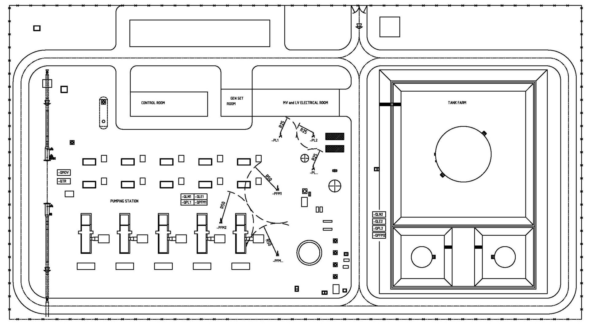
As shown in the lay-out plan above, the electrical circuits for general services are divided into:
1. Normal lighting circuits (-QLN…)
2. Emergency lighting circuits, designed to operate when the power of the normal lighting fails (CIE Publication 17.4) which are divided into: (-QLE ...)
- Permanent emergency circuits in which the emergency lighting fixtures are always powered when normal or emergency lighting is required. (-QLE...).
- Emergency circuit not maintained in emergency, in which the emergency lighting fixtures are in operation only when the power for the normal lighting is out of service. (-QLE ...).
- Combined emergency circuits, in which the lighting fixtures containing two or more lamps, have at least, one lamp supplied by emergency illumination and, the other, by the normal illumination. (-QLE ...).
- Emergency circuits with lighting fixtures with built-in batteries, in which there are emergency lighting fixtures with maintained or not maintained emergency, in which all elements, such as the battery, the lamp, the control unit, the test and the structures of control, where provided, are contained within the unit or adjacent to it (that is, within 1m cable length).
- Emergency circuit with centralized power supply, in which the lighting fixture, permanent or not permanent, is fed from a centralized emergency source (for example by UPS), with possible satellite management. (-QLE ...)
3. Security lighting circuits which are part of emergency lighting designed to ensure the safety of people during the evacuation of an area or of those attempting to complete a potentially dangerous operation before leaving the zone. (-QLE ...)
4. Backup lighting circuits, which are part of the emergency lighting that allows to continue normal activities without substantial changes. (-QLE ...)
5. High-risk areas lighting circuits which are part of the emergency lighting aimed to assuring the safety of the people involved in processes or potentially dangerous situations and to allow appropriate shutdown procedures for the safety of operators and of occupants of the rooms. (-QLE ...).
6. Lighting sockets feederes circuits at 230Vac (-QPL ...)
7. Driving power sockets feeder circuits at 400 Vac (-QPFM…)
8. Tracking systems feeder circuits (-QTR ...)
9. Motor operated valves feeder circuits (-QMOV…)
3. The LED innovation
The technical innovation has brought a radical change in lighting systems, change due to the introduction of new LED lighting fixtures that, at the same luminous flux, have the advantage of absorbing an amount of energy some times up to 70% less the energy required with the use of traditional discharge lamps or fluorescent lamps lighting fixtures.
For this reason, will be possible to revise the basic concepts of circuit sizing which, as standard practice up to today, provided a maximum load of 2 kW for each light circuit, in order to have a homogeneous and unified circuitry for a localized distribution.
Now, on the basis of what described above, such circuits will have less power and, therefore, it will be possible to provide switchboards with several outgoing but with equal total installed/absorbed load.
4. The local systems
Similarly, but without the decrease of load, even the remaining systems mentioned above require a specific engineering for each type of plant, keeping the usual engineering criteria such as:
- Coverage of the areas in order to ensure a proper management and maintenance, with the positioning of 230Vac light sockets within a radius of 25 meters between each other or within a radius of 50 meters for 400 Vac power sockets.
- Placement in a central area for all other types of switchboards such as tracking and MOV, depending on the placement of these utilities respect to the plant.
For the reasons above, the designer of the system, pays great attention for a correct selection of the types of materials, depending on the specific needs of the plant within which such equipment must operate.
Cortem Group, always attentive to these issues and always looking for new technologies to improve its products by reducing the environmental impact both in energy consumption and disposal at the end of life, has, within its manufacturing unit in Villesse, a technical staff for research and development of new technologies.
5. Conclusions
As you can see, the list of variables that contribute to a proper design are varied and not easily predictable in the early stages of the design, so the search for a normalization is an excellent tool to predict the changes in the various stages of the engineering details.